DemiRGB PCB Assembly
For revision 1.2 boards.
Required tools
- Soldering iron
- Solder
- Side cutters
- Small cross head screwdriver
- Scissors
Recommended tools
- Blue painter’s tape
- Heat-resistant soldering pad
- Magnifying glass
- Breadboard
- Multimeter
Assembly
In general, you want to solder components beginning with the shortest (the resistors) and ending with the tallest (the MOSFETs / power regulator and heatsinks). When placing components, you can splay the legs of a component underneath to keep them in place while soldering, or use blue painter’s tape on the top side to hold them down temporarily.
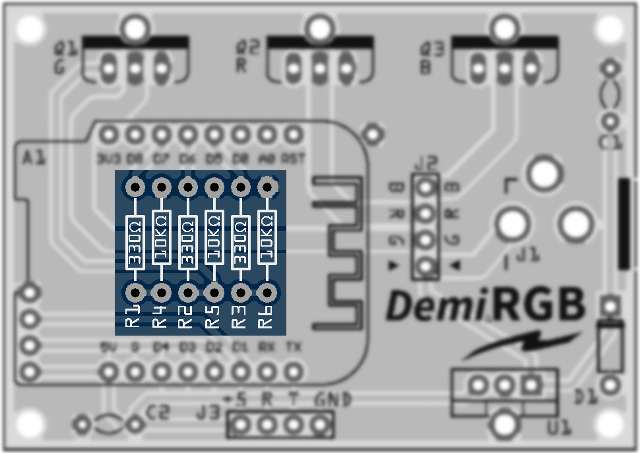
Solder the 6 resistors. R1/R2/R3 are 330Ω resistors, while R4/R5/R6 are 10KΩ resistors. They are arranged in an alternating pattern, so make sure you place them as indicated on the board (330Ω, 10KΩ, 330Ω, 10KΩ, 330Ω, 10KΩ). Resistors are unpolarized and may be placed in either orientation.
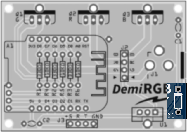
Solder the diode, D1. Diodes are polarized, and it is critical that the side with the stripe (the cathode) be oriented the same as on the board.
If the stripe has rubbed off the diode (it happens), there are several other ways to be sure.
- If the diode still has the paper tape ends attached, the cathode will usually be on the side with red paper.
- Decent multimeters will have a diode test mode.
- Even with an inexpensive multimeter, just set it to resistance and try the ends. If one direction comes up as 0L (out of range, low) or a very low number, flip it around. If it is then high (above 1MΩ), the common end of the multimeter (black lead) will be the cathode.
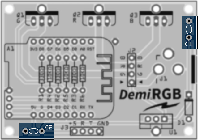
Solder the two ceramic capacitors, C1 and C2. C1 is a 0.33µF capacitor (labeled “334” on the component), and C2 is a 0.1µF capacitor (labeled “104” on the component). Ceramic capacitors are unpolarized and may be placed in either orientation.
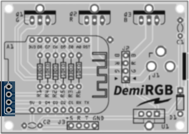
Solder the 4-pin male-to-male right angle jack on the left hand side, J4. Note that the jack should be installed on the top side, even though the silkscreen information is on the bottom. The right angle pins should be arranged so they are facing outwards (to the left).
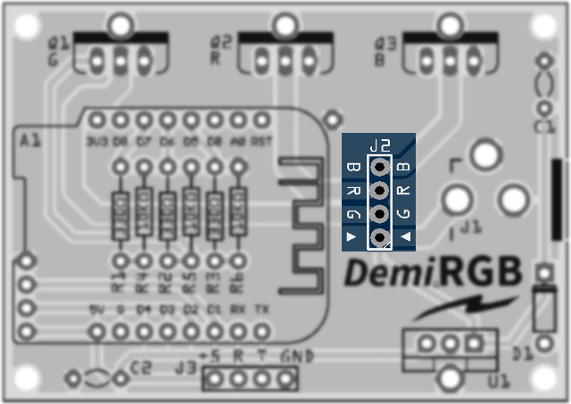
Solder the 4-pin male-to-male round pin jack, J2. Double check you are using the round pin header, as most RGB LED strips use connectors which require round pins.
J3 (at the bottom) is unused and should only be populated if you intend to hack with the UART.
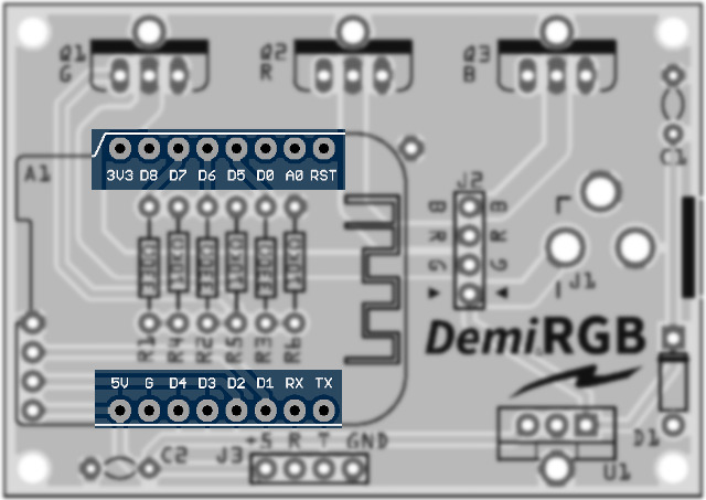
Solder the two sets of 8-pin male-to-female headers on the board for A1.
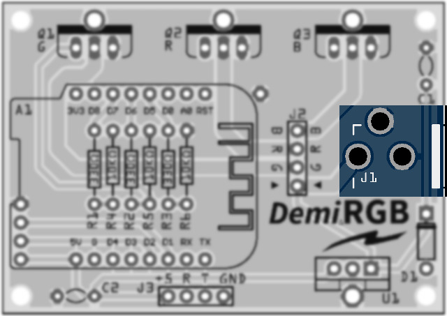
Solder the DC jack, J1. Note that the pins are rather large in the board holes, so use a decent amount of solder to make good contact between the pins and the board, as the jack will need to handle a lot of physical stress.
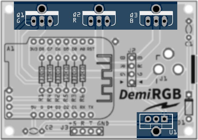
Solder the three MOSFETs, Q1/Q2/Q3, and the 5v power regulator, U1. Before soldering, attach each component to a heatsink, with thermal tape (cut to size) between each component and heatsink. Use an M3 screw and nut to secure each through the heatsink/component. It is recommended that the head of the screw be in the rear (heatsink side) and the nut and extra screw length in the front (component side). Attach snugly but do not over-tighten. Q1/Q2/Q3 receive the smaller heatsinks, and U1 receives the larger heatsink. Solder all 3 legs of each component and the heatsink leg to the board.
- Carefully examine which are the three MOSFETs and which is the 5v power regulator, as they all look nearly identical except for the markings. In particular, the 5v power regulator will have “7805” somewhere on the front markings.
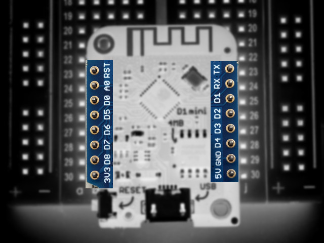
Solder the two sets of 8-pin male-to-male headers on the “D1 Mini” daughterboard (not to be confused with diode D1 on the main board). The pins should be soldered so they are male underneath the daughterboard. If you have one, it is helpful to insert the pin headers into a breadboard before soldering the top of the daughterboard.
- If you plan on hacking on the hardware, you may want to instead use the included long male-to-female headers, with the male pins underneath the D1 Mini and the female pins above. This will give you access to all of the D1 Mini’s pins.
Attach the “D1 Mini” daughterboard to A1 on the main board, so that the USB port is on the outside (left) of the board.